

Using the “Timber sections” module, CYPECAD and CYPE 3D analyse and design timber beams and generic bars.
More information on the analysis and design of timber joist floor slabs can be found on the “Timber joist floor slabs” webpage.
General properties of timber elements in CYPECAD
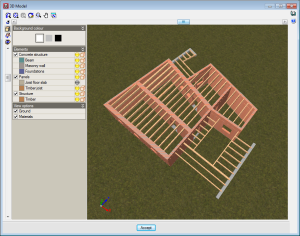
CYPECAD allows users to define, analyses and design timber beams and timber joist floor slabs. These structural timber elements are included in the “Timber sections” and “Timber joist floor slabs” modules, respectively.
The “Timber sections” module is for use in CYPECAD and CYPE 3D, and allows users to analyse and design structural beam-type timber elements and generic-type timber elements. More information on the structural types of bars that can be introduced in CYPE 3D and integrated structures of CYPECAD can be found in the section on “Bar structure types in CYPE 3D” on the CYPE 3D webpage.
More information on timber joist floor slabs can be found on the Timber joist floor slabs webpage.
Implemented codes
The codes implemented for the design and check of the timber joist floor slabs and beams are:
- CTE-DB -SE-M (Spain)
- Eurocode 5
- Eurocode 5 France
- Eurocode 5 Belgium
- NBR 7190:1997 (Brazil)
Section series
To adapt the program to the current market, timber sections have been created, distinguishing between sawn timber and laminated timber, and including the DUO/TRIO series, which are currently very much in use.
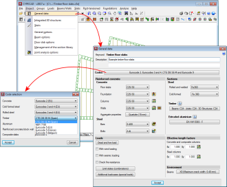
Definition of the material, service class and live load duration
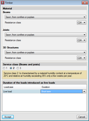
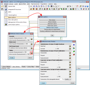
The data CYPECAD and CYPE 3D will use to analyse the timber elements (beams and generic bars of CYPE 3D and integrated 3D structures, and joists – only in CYPECAD-) is defined in the “Timber” dialogue boxes (Project > General data > Timber):
- Material properties
This data is defined individually for beams, joists and bars of 3D structures. In CYPE 3D, the material that is defined affects both “Beam-type” and “Generic-type” structural timber elements. However, in CYPECAD and CYPE 3D, each beam o generic bar can have different material properties. The properties that have to be defined vary and the options that are available for each property will depend on the code that is applied:
- Type
- Origin
- Resistance class
- Category
- “Service class” or “Humidity class”
In CYPECAD, the service class defined is applicable to beams, joists and timber bars of 3D structures, and in CYPE 3D, it is applicable to timber beams and generic bars.
- Duration of loads introduced as live loads
The duration of live loads which affect timber elements is also applicable to any timber element defined in CYPECAD and CYPE 3D.
Introducing timber beams
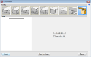
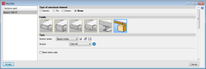
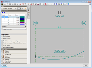
In the “Current beam” dialogue box of CYPECAD (Beam definition tab > Panels > Beams/Walls > Define beam > Timber beams), and in the CYPE 3D dialogue box "Describe" (Bar > New beam > Default beam > Timber beams), users can introduce timber beams.
By introducing timber beams as structural elements in CYPECAD and CYPE 3D instead of as generic timber bar, allows users to use the Advanced beam editor to edit and design these elements.
In CYPECAD, users can define timber beams as “Beam below slab”. In this case, if the timber beam limit timber joist floor slabs, it will be placed below the maximum depth of the floor slab. More information on the elements which include the maximum depth of a timber joist floor slab can be found in the “Introducing timber joist floor slabs” section of the “Timber joist floor slabs” webpage.
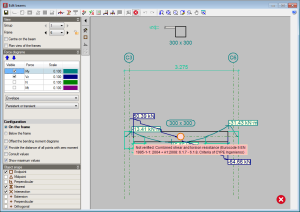
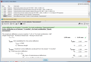
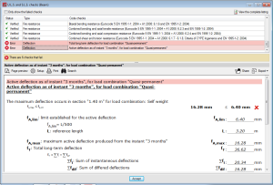
Timber beams design (worst case check reports)
From the “Beams” menu in the “Results” tab, users can access the worst-case checks of beams. This report includes the deflection checks of the timber beams.
These deflection checks are obtained bearing in mind the deflection limits defined in “Beam options” (Project > Beam options).
By introducing timber beams as structural elements in CYPECAD and CYPE 3D instead of as generic timber bar, allows users to use the Advanced beam editor to edit and design these elements.
Fire resistance check of timber beams
The program carries out the fire resistance check of timber elements of CYPECAD and CYPE 3D (timber beams, timber joist floor slabs, and generic timber bars in integrated 3D structures and in CYPE 3D) using the “Fire resistance check” module, which also carries out this check for steel and concrete structural elements.
The data that has to be defined for CYPECAD to be able to check the fire resistance of timber joists and beams is introduced in the “Fire resistance check. General data” dialogue box (Project > General data > Loads > Fire resistance check).
In this dialogue box, users have to define, for each floor group:
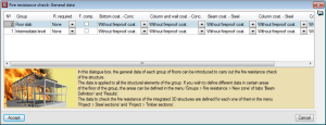
- The required resistance
- Whether or not there are floor slabs acting as compartments
- The coatings of the structural elements:
- Bottom coating of concrete beams and floor slabs
- Coating of columns, shear walls and walls
- Coating of steel beams and joists
- Coating of steel columns
- Coating of timber beams and joists
It is possible to defined different data for a specific zone in a group of floors using the options of the Fire resistance window (Groups > Fire resistance from the Beam Definition or Results tab).
More information on this module, for use with CYPECAD and CYPE 3D, can be found on the Fire resistance check webpage.
User license
For CYPECAD and CYPE 3D to be able to analyse and design timber joist floor slabs, the user licence must include, as well as the permits corresponding to CYPECAD and/or CYPE 3D, the “Timber sections” module.
If, users also wish to check the fire resistance of these elements, they must also hold the “Fire resistance check” module permits.
CYPECAD versions and modules
CYPECAD versions
CYPECAD is available in its unlimited version and also in two limited versions called LT30 and LT50, which contain the same tools and module acquisition possibilities, but have the following conditions:
CYPECAD LT50:
- Fifty columns
- Four floor groups (Floor group: floors which are the same and consecutive)
- Total of five floors
- Walls: one hundred linear metres
CYPECAD LT30:
- Thirty columns
- Four floor groups (Floor group: floors which are the same and consecutive)
- Total of five floors
- Walls: one hundred linear metres
Integrated 3D structures of CYPECAD (also LT50 and LT30) is not technically a module. To define these 3D structures in CYPECAD, users must also have the required permits to use CYPE 3D in their user license and, optionally, modules which are exclusive to CYPE 3D.
CYPECAD Modules
The following modules are those that can be acquired together with CYPECAD or CYPECAD LT:
- Steel columns
- Steel beams
- Joist floor slabs (generic concrete joists)
- Joist floor slabs (in-situ, precast and steel)
- Timber joist floor slabs
- Waffle slabs
- Flat slabs
- Punching shear verification (Also operates as an independent program)
- Composite slabs
- Hollow core slabs
- Post-tensioned concrete slabs for buildings
- Shear walls
- Reinforced concrete walls
- Plane stress walls
- Stairs
- Mat foundations and foundation beams
- Concrete block walls
- Interaction of the structure with the construction elements
- Automatic job introduction: DXF, DWG and CAD/BIM models
- Collective protection systems
Modules common to CYPECAD and CYPE 3D:
- Concrete columns
- Composite steel and concrete columns
- Concrete beams
- Timber sections
- Pile caps (includes strap and tie beams)
- Baseplates
- Footings (pad and strip) (includes strap and tie beams)
- Advanced design of surface foundations
- Fire resistance check
- Parallel analysis with two multiprocessors
- Parallel analysis with up to eight processors
- Joints I. Welded. Warehouses with rolled and welded steel I sections
- Joints II. Bolted. Warehouses with rolled and welded steel I sections
- Joints III. Welded. Building frames with rolled and welded steel I sections
- Joints IV. Bolted. Building frames with rolled and welded steel I sections
- Joints V. Flat trusses with hollow structural sections
- Export to Tekla
Tel. USA (+1) 202 569 8902 // UK (+44) 20 3608 1448 // Spain (+34) 965 922 550 - Fax (+34) 965 124 950